Frequently Asked Questions
Navigating this Document
Click ► Arrow Triangles
 to open a fold in the document.
Open all folds before printing or searching for text in this document.
 [Close All Folds] |
 [Open All Folds] |
General Questions
- ► Where can I get Help?
-
If you need assistance when using the software these are the primary places to look:
- Program Help File: From the Main menu select Help
- Video Tutorials: These are supplied on the installation DVD or can be downloaded from the Vectric website.
- User Forum: The Vectric user forum at www.vectric.com/forum is a very useful resource for information on Aspire along with materials, cutters etc. and also to share knowledge and experiences.
- Email Support: The Vectric Support Team at support@vectric.com
- Support Website: http://support.vectric.com/ provides access to Frequently Asked Questions, Training Materials, Updates and Upgrades, Gadgets and Free Projects for some Vectric software.
- ► What file formats can be used?
-
Aspire will open files that have been saved in the following formats:
Vectors
File Suffix
Format summary
DXF
Drawing Exchange Files from CAD systems
EPS
Encapsulated Postscript from Adobe Illustrator and Corel Draw etc.
AI
Adobe Illustrator
PDF
Portable Document Format for industry standard print data
SKP
SketchUp software files
If the designs are being prepared with software such as Corel Draw or Adobe Illustrator we recommend that you convert the vector geometry and text to curves and switch off all patterns or color fills before exporting, preferably as an EPS file.
Images
File Suffix
Format summary
BMP
Windows Bitmap Format
JPG, JPEG
Compressed format commonly used for digital photographs and websites
GIF
A common web format, usually with a limited number of colors
TIF, TIFF
A compressed format, including a 16-bit version
PNG
More recent format with a good range of properties
3D Models
File Suffix
Format summary
STL
CAD orientated 3D design packages and scanning systems
DXF
Many CAD systems - data must consist of meshes or triangles
3DS
3D Studio and many other animation orientated packages
OBJ
Wavefront
SKP
SketchUp software files
V3M
VectorArt 3D clipart models
- ► What are the limitations of the Trial Versions
-
The Trial Versions will let you use all functions within the software with the exception of saving the toolpaths and performing some Export functions.
The Pro Versions of the Trials also do not allow you to use additional Gadgets.
There are a collection of special "trial version specific" files made available for each program that are setup so you can save the toolpaths from them and verify compatibility with your CNC machine by actually machining the samples.
For Aspire, VCarve Pro/Desktop and Cut2D Pro/Desktop these are found in the Getting Started Tutorials from the Video Tutorial Browser. For more information about these tutorials please use the link for "How do I use tutorials in the Trial Edition?".
You can also access the Trial Projects from the option Evaluation Files to Machine found on the first screen of the Trial.
Cut3D comes with a set of Trial files that are accessed from the trials start screen.
PhotoVCarve can work with any photo image however restricts the toolpath output by applying a watermark to all images.
- ► What are the minimum requirements for my PC to run Vectric software?
-
The Aspire, VCarve, Cut3D, PhotoVCarve and Cut2D software products will all run on virtually all home PC's and do not require any special hardware or graphics card.
Aspire, VCarve Pro/Desktop and Cut2D Pro/Desktop software is 64Bit and 32Bit, and will work on both 32bit and 64bit Operating systems.
Cut3D and PhotoVCarve software is 32bit, and will work on both 32bit and 64bit Operating systems.
Vectric Software does not support Windows 8RT as this is not a full edition of Windows.
The minimum PC specification for Aspire and VCarve Pro/Desktop is: Computer: 2 Ghz multi Core CPU
2Gb RAM with Windows XP(SP3), Windows Vista & Windows 7, 8, 8.1 or 10
300 Mb Disk space (Program)USB drive required for USB Media Pack if purchased.
7.7GB Additional disk space required if you wish to store the tutorials and clipart supplied, on your hard drive.
Display: 1024 x 768 Graphics display Operating System: Microsoft Windows XP (SP3), Vista, 7, 8, 8.1 or Windows 10 with 2Gb RAM The minimum PC specification for Cut2D Pro/Desktop is: Computer: 2 Ghz CPU
2Gb RAM with Windows XP(SP3), Windows Vista, Windows 7, 8, 8.1 or 10
250 Mb Disk space (Program)USB drive required for USB Media Pack if purchased.
2GB Additional disk space required if you wish to store the tutorials and clipart supplied, on your hard drive.
Display: 1024 x 768 Graphics display Operating System: WindowsXP (SP3), Vista, Windows 7, Windows 8 or Windows 10 with 2Gb RAM The minimum PC specification for Cut3D and PhotoVCarve is: Computer: 1 GHz Pentium 4
512 Mb RAM
60 Mb Free disk space
CD DriveDisplay: 1024 x 768 Graphics display Operating System: Windows XP (SP3), Windows Vista, Windows 7, Windows 8 or 8.1, Windows 10 Other: A PDF reader program (such as Adobe PDF Reader) is required to read the documentation. Note: The Intel 82810 & 82815 integrated graphics cards must be set to run in 16 bit color mode.
- ► How many computers can I install my Vectric software on?
-
Vectric's license allows any of our software programs to be installed on up to 3 PC's for a single user.
If access to any one of the computers is shared with work colleagues, or anyone who is likely to access the software, then the software must only be installed onto one computer.
- ► Do you have educational pricing for Vectric Software?
-
All Vectric products are available for purchase by registered educational establishments and we have very special pricing available for classroom licenses.
Please send an email to This email address is being protected from spambots. You need JavaScript enabled to view it. for further information.
Educational purchases cannot be made via the Webstore front, only via the sales team.
- ► Can I run the Trial Version in a non-English version?
-
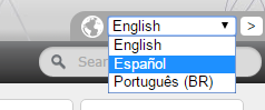
Yes, for Aspire, VCarve and Cut2D, the Trial software is available in alternative languages through our Spanish website.
While the website is in Spanish, the Trial installers have our full range of International languages included.
For PhotoVCarve and Cut3D, the Trial Versions are available only in their English version.
If you are interested in what language versions may be available for purchase, contact This email address is being protected from spambots. You need JavaScript enabled to view it. and we will help you.
- ► Why do I receive an error opening recent files?
-
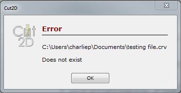
If you receive a warning similar to this:
e.g. File Missing
The file you are trying to open has either been deleted or moved to another locaton on your computer.
Click OK, and use "Open an existing file" to manually locate your file.
- ► Why do I get "An unknown error occurred while accessing an unnamed file" when saving to a network location?
-
Errors when saving across a network is likely caused by minor faults in a network connection.
It is more reliable to work from the local drive, and less likely to result in lost or corrupted files.
Should you encounter this error when saving, save your projects to a local destination and then back them up to your network accessed storage once completed.
- ► Where is the Vectric Files folder?
-
In Windows Vista, 7, 8 and 10, the Vectric Files folder is most easily located using the Documents item under Libraries in Windows Explorer. Following the default installation, the folder is: C:\Users\Public\Documents\Vectric Files
In Windows XP the same folder is C:\Documents and Settings\All Users\Documents\Vectric Files
- ► Where do I look to find the Tool Database on my PC?
-
Start the program and use the File Menu ► Open Application Data Folder. This will open a new window showing all the program's support folders. Select the ToolDatabase folder to find the Tool Database file.
- ► Where do I look to find the Post Processors folder on my PC?
-
Start the program and use File Menu ► Open Application Data Folder. This will open a new window showing all the program's support folders. Select the Postp folder to find the Post Processors.
- ► Where do I look to find the Gadgets folder on my PC?
-
Start the program and use File Menu ► Open Application Data Folder. This will open a new window showing all the program's support folders. Select the Gadgets folder to find the Gadgets.
- ► What is the latest software version available?
-
To check which version of the software you are running, please run the software and click the Help Menu ► About....
If you are not running the latest major release version as above i.e. you are using Aspire 8 instead of Aspire 9, then you may want to learn more about the new and exciting features that have been added to your product.
You can check out the latest enhancements as well as our affordable upgrade options by visiting: http://support.vectric.com/upgrade
If you are running an older version then you may be entitled to update to the latest minor release of that software. You can view all available updates by visiting: http://www.vectric.com/support/program-updates.html
- ► What is the difference between Updates and Upgrades?
-
Each version of the software comes with a Version Number.
For example: VCarve Desktop V8.012
In this example, VCarve Desktop is Major Version 8 and Minor Version 0. The following 2 numbers then give it as Patch number.
When you do a software Upgrade, you are doing a transfer from one Major Version of the software, to another Major Version of Software. These Upgrades are almost always done via the Vectric Store Upgrade Page, or via an email notification to your registered email address.
For example: This could Upgrade VCarve Desktop v8 to:-
Aspire v8 or higher when released
VCarve Pro v8 or higher when released
VCarve Desktop v9 or higher when released
When you do a software Update, you are updating the Minor software version and the Patch number.
Currently all Vectric customers are able to download the latest Minor Version update for the Major Version they own.
For example:-
Aspire v8.007 ► Updates to Aspire v8.012
VCarve Pro 7.0 ► Updates to VCarve Pro 7.514
All Software Updates and Patches can be downloaded within the software by going to Help Menu ► Check For Updates. This will begin the download of the latest available Updates for your software, and will require an internet conenction. For Manual Patching visit the Software Updates Page to download your patch. If a manual patch does not automatically find the software version when used, it is likely that you do not have the correct Update for your Major Version.
Summary:-
Major version releases include new Major features for the software, such as new tools and important features. These are usually Paid Upgrades.
Minor Version releases include some smaller new features or adjust existing features to make them easier to use. These are usually free Updates.
Patch releases include minor tweaks and fixes to ensure existing features work as intended. These are always free updates.
- ► What are Gadgets?
-
A Gadget is an external add-in program that performs a specific task for our Aspire, VCarvePro and Cut2DPro products only. New Gadgets are simply copied to the Gadgets folder (one of the Application Data Folders) and when the program is restarted, they will be available from the Gadgets menu.
The program is shipped with a number of Preinstalled Gadgets and more may be made available from the Vectric web site over time.
A section of our website is dedicated to Gadgets: http://gadgets.vectric.com.
- ► What is the Vectric License Transfer Policy?
-
Can I transfer my Vectric software?
Unlike the vast majority of software companies, Vectric does allow the original purchaser of a software licence to transfer it under certain circumstances, and subject to a licence transfer fee. However this is NOT an unrestricted right of transfer, and Vectric reserve the right to refuse to transfer the licence, at its sole discretion, if it reasonably believes there is evidence of the license conditions having been broken. If you upgrade a product from say Version 4.0 to Version 5.0, you still only own one licence and that is now for Version 5.0: you no longer have a valid licence for V4.0 and so the licence for the older version obviously cannot be transferred.
Software licence purchased directly from Vectric or an authorised Vectric partner
If you have purchased a single user license directly from Vectric or one of our authorised partners, we would usually allow you to transfer the single user license to another individual or company, subject to the licence conditions having been adhered to and the payment of a licence transfer fee (currently $50).
You cannot transfer a license that you have not directly purchased (i.e. one that has been transferred to you, from a previous licence holder). The original purchaser of the software licence can transfer it once, but subsequent owners cannot.
If you upgrade a product to a more expensive one, you cannot subsequently transfer the initial product licence. e.g. if you upgrade VCarve Pro to Aspire, the VCarve Pro licence has been 'traded in' against the Aspire licence and you no longer have a licence for VCarve Pro.
Software licence transferred from a previous original owner
If you have obtained a licence from a previous original owner, you cannot subsequently transfer that licence to a new owner, unless the software licence was originally bundled with a machine, and you are transferring the machine along with the licence (see section below for this case). The transfer rights for the software are only available to the original purchaser of the software from Vectric or one of our authorised partners. If you are planning to buy a 'used' licence of Vectric software from somebody, it is essential that you contact Vectric first via This email address is being protected from spambots. You need JavaScript enabled to view it. to ensure that the licence in question can be transferred.
Software licence originally bundled with a machine tool
If you received Vectric software bundled with a machine tool from an approved Vectric partner, you may transfer the software along with that machine tool, providing that you have not used the license to upgrade to a different product. This applies even if you are not the original purchaser of the machine.
If you have upgraded the software, the upgraded product would need to be transferred along with the original media supplied with the machine. You do NOT have to transfer the software licence when you sell the machine, but the new owner of the machine will need to purchase their own copy of the software if they wish to use it in this case.
Educational Software Licence
Educational classroom licenses cannot be transferred.
Please email details of any license transfer requests to This email address is being protected from spambots. You need JavaScript enabled to view it.
- ► I Need to Email Support
-
If you ever require help with your project, in particular any project that involves issues with your toolpaths and generating toolpaths we will need to see the original project files to be able to give accurate advice.
When preparing to email This email address is being protected from spambots. You need JavaScript enabled to view it. to request assistance, please check the following points.
- Make sure you list the exact name of the Post Processor you are using to create your toolpaths. There are many Post Processors with similar names and they can often be mistaken for each other.
- Once you have created your toolpaths, save a copy of your project to send to us. It can be very helpful if we can see your toolpaths exactly as you created them in the project.
- If you are having trouble with a particular toolpath and its cutting results, send the Gcode file you have generated along with your project.
- If you are experiencing a crash with the software, and can replicate it, save a copy of the project right before the crash and detail the steps you take to make it crash. This will provide the steps we need to fault find the cause of the issue.
It can help to compress (ZIP) your files. This will make them smaller to send via email, meaning you will spend less time uploading them.
Lastly, always send your support requests from the email address you registered your software from. This will reduce any delay while we confirm your registration.
- ► How do I use tutorials in the Trial Edition?
-
- Open Trial software
- Click Tutorial Video Browser in left hand panel
- Click View Tutorials under By Catagory
- Click Wing Spar under the Getting started heading
- Click Download Files
- Open downloaded installer and run it, following on screen instructions
- Go back to Internet browser witht he Tutorial Window and press F5
- This will change the "Download Files" to "View Files"
- Click on "View Files" and you will be able to open the CRV files which contain toolpathing you can export with the appropriate Post Processor for your machine. Please be sure to edit the existing toolpathing to correct the tool settings and Cut depth to be suitable for your machine to avoid creating commands that may damage your machine and toolbits.
- ► How do I Uninstall Vectric Software?
-
This Article applies to all Vectric products and versions.
On installation, all Vectric products will create a listiing in the Windows Programs and Features control panel applet ('Add or Remove Programs' in older versions of Windows).
Windows 8, 8.1 or 10
- Open the Windows Start menu (Windows Key). From the Start screen, start typing Control Panel (the search should autofill after a few characters).
- Click on Control Panel from the Apps search results, in the opened Control Panel window, select Programs and Features
- In the Programs and Features window, you will see the Vectric product listed amongst the other applications installed on your computer. Select the Vectric application that you wish to uninstall and click on the Uninstall button.
Windows Vista or 7
- Open the Windows Start menu (Windows Key). From the Start click on Control Panel
- Depending on your view options click either on Uninstall a program or Programs and Features
- In the Programs and Features window, you will see the Vectric product listed amongst the other applications installed on your computer. Select the Vectric application that you wish to uninstall and click on the Uninstall button.
Windows XP
- Open the Windows Start menu (Windows Key).
- From the Start screen, click on Settings then click on Control Panel. In the Control Panel window click on the Add or Remove Programs applet.
- In the Add or Remove Programs window you will see the Vectric product listed amongst the other applications installed on your computer. Select the Vectric application that you wish to uninstall and click on the Change/Remove button.
- ► How do I find which version of the software I am running?
-
Select Help Menu ► About Aspire... from the Main Menu and a dialog window will open that shows the exact version you are using.
- ► How do I find and install an update when a newer version of the software is available?
-
Select Help Menu ► Check for Updates from the Main Menu and if this tells you an update is available, follow the prompts to download and install the update automatically.
You can also download the latest versions from the Customer Portal.
- ► How do I download my free Clipart?
-
New Version 8.0 and higher sales of Aspire and VCarve Pro/Desktop come with a collection of free Clipart files to use in these versions of the software.
Due to their size they are not included with the main software download.
To access them you can log into your Vectric Portal account and click on the View Downloads for your software.
This will load a page with your software download and licence details, and when you scroll down the page you will see all of your Clipart links to download from.
Some of these are large downloads (more then 200MB) and will take some time to download depending on your interent connection.
Alternatively, you can install the Clipart from your Media DVD if you selected this option when purchasing the software. If your software was bundled with your CNC machine on purchase, you will have a Media DVD. Load the DVD into your DVD drive on your PC and select the option to install the Clipart and follow the on-screen instructions.
- ► How do I add new material image files to the available list?
-
From Aspire 4 / VCarve Pro 7 onwards you can add new images to the Material Images folder in your Vectric Files folder.
In Aspire 3.5 / VCarve Pro 6.5 or earlier you will need start the program and use the File Menu ► Open Application Data Folder.... This will open a new window showing all the program's support folders. You can add new material image files to the Bitmap Textures folder.
You will need to restart the software for your new image files to appear in the material drop-down lists.
- ► How do I access installed Video Tutorials?
-
For Version 8.0 and above, you can access the tutorials through the tutorial video browser which is accessed from within the program when you first start the software. There is a link to it on the left side of the interface under the Recently Opened Files section. If you have a disk or USB stick then you can download the tutorials to your hard drive where you can access them in your Vectric Files folder on your PC.
For VCarve Pro 7.0 and Aspire 4.0 there is an option to install the video tutorials from the Installation Media. Choosing this will copy all the tutorial videos and files into the Tutorial Files folder which is located under the Vectric Files folder on your PC.
The installation will also create a shortcut icon for your default Web Browser on your Desktop which will be labeled with the appropriate software name and version. Clicking on this will open a Tutorial Browser that can be used to navigate the different sets of tutorials and access the videos and related files.
- ► How can I compare the features of each Program?
-
When trying to decide which Vectric program will best suit your needs, you can use the Software Comparison Chart.
If you still need more information, asking on the User Forum should get you some answers from experienced users and you can download the Trial Versions of the programs and work with your designs for free.
- ► Dropbox and File Sharing Folders
-
While Dropbox and other File sharing distribution methods are helpful for sending project files between friends and colleagues, for best practices we recommend having a local folder on your Hard Drive to save your .CRV and .CRV3D Project files from Aspire/VCarve/Cut2D, before then copying them from this folder into the special Dropbox (or other Shared) Folder.
This is because with the way File sharing works, if a friend or colleague accesses your file when you go to save (Or the system Syncs the file at that time) then it can lead to file corruption and lost data.
Saving the Project file directly to your local Hard Drive prevents this from happening, and allows you to then safely copy and paste the correctly saved file to your Shared Folder.
This has the added advantage that is someone edits your shared file, you can still access the original saved on your local computer if required.
- ► Double Clicking loads older version
-
After updating to a new version, files (.crv / .crv3d) still open in the older version when double clicked.
This can occur if the previous major version of a product is not uninstalled before the newer version is installed.
Windows fails to correctly update the Windows Registry keys to open the newer version when requested.
To correct this, a couple of steps need to be taken:
- Uninstall the previous version (be sure to back up any custom Post Processors or Toolbit database settings first if you have not already transferred them to the new version)
- Reinstall the New version.
Now check to see if this has managed to correct the issue in Windows by double clicking one of your .crv / .crv3d files. This should allow the New Version to over write the effected Registry keys now that the original versions software is no longer installed.
This reinstallation must be done with a computer account that has full write accesses rights to the Windows Registry.
- ► Can Vectric software run the CarveWright machine?
-
None of the Vectric products can directly run the CarveWright machine, however:
- Aspire can be used to create and export 3D Models in STL format, which can then be imported into the CarveWright software using their optional STL Importer.
- A 3D model may be saved from Aspire as a Grayscale height-map image that can then be opened into the CarveWright software, which will automatically recognize the grayscale as a carvable relief model.
- In addition, you can export vector drawings as DXF format, which can be imported into the CarveWright software via their optional DXF Importer. You can find more information on the STL and DXF Importers on the CarveWright website.
- ► Can I open the files created in the Trial Version of the software into the full version?
-
Yes, but only on the same computer that the Trial Version was installed on.
Once you have opened the files in the release version and resaved them, you can then open them on any computer running the program.
If you do have files that were created in the Trial Version that you need to keep and use, it is a good idea to open and save them as soon as possible after installing the release version as any problems or hardware changes to the PC could prevent the program from opening those files from the Trial Version.
2D Design - Vectors & Images
- ► Can I open Corel Draw files?
-
Yes, Corel Draw files can be opened in Aspire, VCarve and Cut2D but not directly as CDR files. The design needs to be exported from Corel using the EPSfile filter, which is very easy to do:
- Select the required lines / shapes / geometry in Corel
- Remove any Fill Patterns and set the Line Thickness = Hairline
- From the File menu select Export
- Tick the option Selected only
- From the Files of Type select the EPS - Encapsulated Postscript option
- Click the Export button
- Click the option to Export Text as Curves
The file can now be opened / imported and toolpathed in Aspire, VCarve and Cut2D.
- ► How can I change the Job / Material Size?
-

The material size for a job can be changed at any time by selecting Edit Menu ► Job Size and Position or the Job Setup icon in the Drawing Tab to open the Job Setup form.
The Units, Width, Height, Thickness and Z Origin can all be changed on this form.
The origin for the job can be specified to be any of the four corners or the middle of the job, and an offset distance can be entered to move the selected origin by the required X and Y distance.
Checking Center vectors in material will automatically reposition the vector design central to the new material size.
Important:If the Z Origin is moved, all calculated Toolpaths MUST be recalculated.
We recommend that you always recalculate toolpaths whenever the material has been changed. This will ensure the toolpaths cut correctly on the CNC machine. This can be done very quickly by using the Recalculate All Toolpaths icon:
 in the Toolpath tab.
 - ► Will the Vectric programs allow mathematical equations to be calculated?
-
Where appropriate, numerical edit boxes support simple math calculations.
Instead of working out a value, you enter an expression directly into the edit box using Special Calculation Characters as needed and then press the = (equal) key.
As soon as the = key is pressed, the program will evaluate the expression and fill the edit box with the results.
- ► Why group vectors?
-
The ability to group vectors is a big advantage for the user. Grouping takes two or more vectors and creates a single object (group) that can be moved around and manipulated without the individual vectors changing their position relative to each other.
At any time, Grouped vectors can be ungrouped to allow changes to be made.
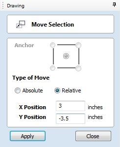
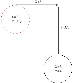
- ► When moving a vector using the Move Selected Objects tool, what is the difference between Absolute and Relative modes?
-
Absolute mode will move a vector or component using the drawing coordinates.
For example, you have a circle with its center at X = 3, Y = 7.5 and you want to move it to X = 6, Y = 4. Select the circle and press M, the shortcut key for the Move Selected Objects tool, then select Absolute and the center anchor point. Change the value in the X input box to 6, the value in the Y input box to 4 and select Apply to perform the move.
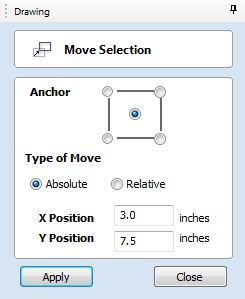
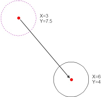
Relative mode will move a vector or component from its current position by the number of units entered in the X and Y input boxes.
Using the above example, you would select Relative and enter +3 in the X input box, -3.5 in the Y input box, then select Apply to perform the move.
Note: An anchor point is not required in Relative mode as the entire shape will move the same number of units in X and Y based on its original position.
- ► What do the different line colors mean?
-
Selected vectors are drawn in .
Usually, selected vectors are drawn as dotted lines but Grouped vectors are drawn as solid lines.
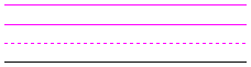
The top three lines are selected.
The top two are grouped together.
The bottom line is not selected and will be the color of the layer it is on.
See the Layers section for more. - ► What is the difference between Ungroup back to original objects layer and Ungroup onto groups layer?
-
Vectors remember what layer they were originally created on, even after being grouped. If you need to ungroup them, you have two options.
- Ungroup back to original objects layer: After ungrouping, the vectors will return to the layer they were created on.
- Ungroup onto groups layer: After ungrouping the vectors will stay on the current active layer.
- ► What is an open or closed vector?
-
Vectors can be open or closed.
- An open vector is a vector that does not join back with itself and the easiest example to visualize is a line.
- A closed vector is one that joins with itself to form a shape with good examples being a circle or rectangle.
Sometimes you can have what looks to be a closed vector but is in fact an open vector. This can cause problems when setting up toolpaths, as some toolpaths treat open vectors different from closed vectors.
There are two quick ways to find whether a vector shape is open or closed:
- You can use Edit ► Select All Open Vectors and see which ungrouped vectors become highlighted or...
- Select the vectors you want to check and use the
 Join Open Vectors tool:
This tool will tell you how many of the selected vectors are open and how many are closed.
Join Open Vectors tool:
This tool will tell you how many of the selected vectors are open and how many are closed.
- ► What is a node and how do I use them?
-
One of the fundamental building blocks in the program are vectors and vectors are two or more nodes joined by lines, Bezier curves, Arcs or a combination of these. The position of the nodes, whether they are smooth or not and the position and strength of their associated control points will dictate the path (shape) that the vector follows between nodes.
You can see and use nodes after selecting a vector and pressing N to enter Node Editing mode.
Node Editing is a very powerful feature, allowing the user to precisely modify a drawing, troubleshoot problems with vectors, and help setup some types of toolpaths.
- ► What fonts come with the program?
-
The program offers a selection of Single-Line fonts suitable for efficient engraving as well as being able to use all the Windows True-Type Fonts that are installed on your PC.
The font is selected in the Forms that create Text:
- ► What are the Special Calculation Characters?
-
- See Also:
- Shortcut Keys
In addition to performing calculations using numbers with standard math operators (+,-,*,/,^, etc.), the program recognizes several Special Calculation Characters to simplify common operations. These are shown in the table below with examples of how they are applied.
Character
Name
Example
Description
W or X
Material Width
w/2=
Half of the material width
H or Y
Material Height
H*2=
Twice the height of the material
T or Z
Material Thickness
t-0.25=
0.25 units less than the material thickness
P
PI (3.141593)
P*10^2=
Circumference of a 10 radius circle (π.r2)
I
Imperial Conversion
25.4*i=
Converts 25.4mm to inches
M
Metric Conversion
2*M=
Converts 2 inches to millimetres
'
Feet
2'+10=
34 inches (2 feet and 10 inches)
- ► What are the Node Editing Short-cut Keys?
-
- See Also:
- Shortcut Keys
Node Editing is a very powerful feature to assist you when working with vectors. You enter Node Editing mode by selecting the vector you want to node edit and then either pressing N, the shortcut key or using the
 Node Editing icon.
Shortcut key Description I Insert a Point D Delete Point / Span S Smooth / Unsmooth Point C Cut Vector opens the vector B Convert span to Bezier A Convert span to Arc L Convert span to Line P Makes the selected node the Start Point for machining X Displays a single node's X and Y location properties X Changes the X co-ordinate position of selected nodes to match the position of the first one (when more than one selected) Y Changes the Y co-ordinate position of selected nodes to match the position of the first one (when more than one selected) H Enter horizontal mirror mode (press again to exit) V Enter vertical mirror mode (press again to exit) Right
mouse clickOpens context sensitive menus Ctrl + Z Edit Undo Ctrl + Y Edit Redo Ctrl + C Copy the selected vectors Ctrl + V Paste the selected vectors Ctrl and Drag Pastes a copy of the selected vectors each time the left mouse button is released. Ctrl + X Cut the selected vectors Alt and Drag Moves the object either horizontally or vertically aligned with its original position Ctrl + Alt and Drag Creates a copy of the original object horizontally or vertically aligned to its original position Ctrl + N Create New file Ctrl + O Open an Existing file Ctrl + S Save file Ctrl + I Import file Page Up Vertically tiles the 2D View and the 3D View window so you can see them both simultaneously. Currently Selected window is on the left - typically best to select the 2D View first when doing this.
Page Down Horizontally tiles the 2D View and the 3D View window so you can see them both simultaneously. Currently Selected window is at the top - typically best to select the 2D View first when doing this.
- ► What are the Keyboard Short cut Keys?
- Aspire has a very complete set of Shortcut keys which are described here. near the end of the Help Documentation.
- ► What are some problems and solutions for importing DXF files?
-
When importing DXF files in from other CAD systems, such as AutoCAD, TurboCAD, Rhino, etc., the files will be opened in the original size and position.
- Problem: Vectors did not import correctly
-
DXF files from other CAD systems may often appear as individual lines and arcs after being imported and cannot be V-carved or pocketed between unless the vectors are joined together using the tools supplied within Vectric Products.
These lines can be profile machined using a Profile-On toolpath, but the individual vectors will machine separately which may result in very jerky machine movements and slow machining times. - Solution: Join the Open Vectors
-
Use the Join Open Vectors tool to join the lines and arcs together so they can be machined more efficiently.
The Join Open Vectors tool can be found within the Edit Objects section of the Drawing Tab in Cut2D, VCarvePro and Aspire.
In addition, Aspire and VCarve Pro have the ability to convert vectors into all lines, all Bezier Curve or all Arcs using the Fit Curves to Vectors tool which can greatly improve cut quality on some machines.
- Problem: DXF file fails to import
- If a DXF file fails to import, it may be due to the DXF version or the DXF file contains entities that Vectric software does not support.
- Solution: Export in another format
- If this is the case, try exporting the file again from the original CAD system in AutoCAD R12 or R14 format as these tend to be more compatible. The ability to export in older versions is normally offered by all major CAD systems. If needed, please consult your CAD application documentation for full details on exporting vectors.
- Problem: Imported Vectors do not contain original Bezier Curves
- The DXF formet does not support Bezier Curves, and can only save Arc curves and Straight lines.
- Solution: Export in another format
- In your original application, use a different format to save your vectors, such as Ai or EPS. Alternatively, modify your design before saving to convert the Bezier curves to Lines and Arcs, which will export correctly in a DXF file.
- ► Special Characters - Draw Text
-
Windows has support for a multitude of characters not seen on the Keyboardsuch as: ¢, ¥, ½, ©, and ¿.
In Vectric software that has support for Drawing Text, you can use the Windows Character Map to copy and paste these special characters into the Text editor to use them in your designs.
You can also use the ALT+ combination to type these fonts, and the combinations for each character can be found in the Windows Character Map.
You must also have selected a font that has support for these special characters. If you select a font that does not have support for these characters they will appear as a blank box, or some other generic symbol. There are to many variations on the Windows fonts to list the supported types here.
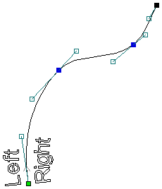
- ► How do you determine which side of an open vector is the right or left?
-
Select the vector and press N, the short-cut key for Node Editing. The small green square at one end of the vector is called the Start Point. If you start at the Start Point and follow the vector toward the node at the other end, the right side is on the right, the left side on the left. It may also help to visualize walking along the vector from the green Start Point to the other end.
- ► How do I display all the Alignment icons on the Drawing Tab?
-
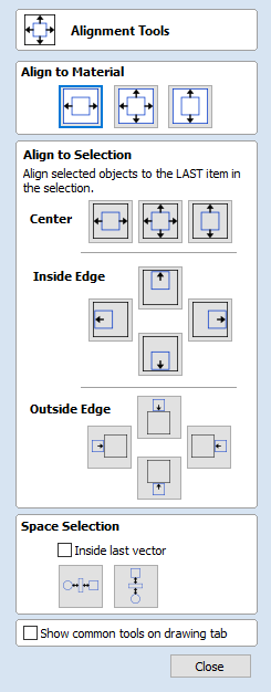
By default VCarve 7.0, Aspire 4.0 and higher will display a single icon to access the
 Alignment Tools Form.
If you want to display more Alignment icons on the Drawing Tab you can check the option at the bottom of the Alignment Icons form:
Alignment Tools Form.
If you want to display more Alignment icons on the Drawing Tab you can check the option at the bottom of the Alignment Icons form:
Checking this will add a section of icons to the Drawing Tab containing the major alignment options. If you have limited screen area you can uncheck this option to return to the default behavior.
- ► How can I work with a drawing that has both metric and imperial measurements?
-
First, setup your project for the units you want (inches or mm). Then, when you are provided a measurement using the other units, you can use the program's ability to evaluate mathematical expressions in the data input boxes to quickly convert the measurement to the needed units.
- To input a measurement given in inches to its metric equivalent, you would enter the inch value in the data input box, followed by *m=. For example, to enter 3 inches in mm, in the data input box you would type 3*m=. As soon as you press the = key, the input value will change to the metric equivalent of 76.2 mm.
- To input a measurement given in mm to its imperial equivalent, enter the mm value in the data input box followed by *i=. For example, to enter 130 mm in inches you would type 130*i= in the data input box, again without the quotes. As soon as the = key is pressed, the input value will change to the imperial equivalent of 5.1181 inches.
- ► How can I import the image if my PDF does not contain vector information?
-
PDF files can contain vector information, bitmap information or a combination of both. If you cannot successfully import a PDF file and get a message that it only contains bitmap data, your only option is to convert it to an image format the program can import using one of the following methods:
- The quickest and easiest way is to open the image in a viewer (depending on your PC, double clicking on the file name will normally open the image in an installed program), then use Print Screen or some other type of screen capture program to capture the image and save in a format that can be imported.
- You may have another program installed on your PC that will open the PDF image and allow you to export or Save As in a format that can be imported successfully.
- ► How can I close an open vector?
-
If you have multiple open vectors you want to close, the easiest approach is to use the
Join Open Vectors tool.
This very powerful tool will show you how many open vectors are currently selected and how many will be closed using the current Tolerance setting once you select Join.Note: Your design may have open vectors as part of it's design, such as lines. Keep this in mind as you work to join only the open vectors that need to be joined.
The Tolerance setting determines how close two vector ends must be for the Join open vectors tool to be able to join them. Sometimes you need to increase the Tolerance setting until they will all close, but be careful with larger values as vectors may join incorrectly. Be sure to check the vectors carefully after you select Join to verify the results. If the results are not what you want, select Edit Menu ► Undo to reverse the operation and enter a smaller Tolerance value. Try to join as many as you can properly do with this tool, then use the next technique to join the remaining ones.
If you only have one vector to join, or a unique situation such as a very large gap, these three additional Join Tools may be a better approach. The tool names describe how the tool will fill the gap between the vector ends.
- ► How can I change the Start Point of a vector?
-
Select the vector and press N, the short-cut key for Node Editing.
If a node already exists where you want the Start Point to be, you can either hover the mouse pointer over it, right-click to open the Node Editing menu ► Make Start Point or hover the mouse pointer over the node and press P, the short-cut key to Make Start Point.
If a node doesn't exist where you want the Start Point to be, hover the point of the mouse cursor over the spot you want the Start Point to be and press the short-cut key P. This will create a new node at that spot and make it the Start Point, all in one operation.
Note: The Start Point must be at one end of an open vector but can be anywhere on a closed vector.
- ► How can I change text spacing (kerning)?
-
The
 The Edit Text Spacing and Curve tool found in the Drawing Tab allows precise adjustment of text.
- ► How can I add more fonts?
-
Additional True Type and Open Type fonts (.TTF) can be obtained from many sources and available to use once the font has been properly installed the Windows Font Directory and the program restarted.
This is not hard to do and typically if you right click on the font file, it will give you the option to install the font. If that option is not available, the exact process can be found in the Help Document for your version of Windows.
The included Single Line Fonts are installed during the program's installation and cannot be changed or added to.
- ► Do I need to use layers?
-
No, you do not need to use Layers, but understanding and learning how to work with them can dramatically increase productivity and make complex jobs much easier to organize and work with.
Some examples where Layers can help you:
- You can organize Layers by the toolpath that will be used, such as drilling, pocket, V-carve and cutout. Used in conjunction with Toolpath Templates and this becomes a very powerful production tool.
- A different color can be assigned to each Layer, helping to visually organize a complex project in the 2D Design window.
- Layers can be made visible or invisible, allowing a complex project to be worked on one portion at a time.
- Layers provide a quick way to create backup copies. Select the vector(s) you want to backup, right-click and select Copy to Layer. Create a new Layer, call it Backup or similar, and uncheck the box to make it invisible.
- When you import a bitmap or vectors from another source, a special layer will be automatically created for this. After performing the operations you need, those layers can be deleted or made invisible.
- ► Can Vectric software run plasma/water jet machine tools?
-
Vectric software is designed specifically to be used with 3-Axis CNC machines and has not been optimized for use with a Plasma or Water Jet machine, however some users have successfully used it to operate this type of equipment.
Aspire 4.0, VCarve 7.0 and higher include an option to add plasma loops onto acute corners of toolpaths.
We would recommend looking closely at the options available in the Trial Version of each program before specifically purchasing them for use with these types of machines. Another good source of information on how the software has been used sccessfully is to search the Main Forum.
- ► Can I work with an image file (bmp, tiff, jpeg etc.)?
-
You can import the following file types into Aspire, VCarve, Cut2D (Pro/Desktop):
File Suffix
Format summary
BMP
Windows Bitmap Format
JPG, JPEG
Compressed format commonly used for digital photographs and websites
GIF
A common web format, usually with a limited number of colors
TIF, TIFF
A compressed format, including a 16-bit version
PNG
More recent format with a good range of properties
Once imported, you can use the
 Trace Bitmap tool to automatically trace the image or you can manually trace the image using the drawing tools.
Aspire also offers the ability to create a 3D component directly from a bitmap image using the
 Create Component from Bitmap tool.
 - ► Can I use a Snap Grid or Guide Lines to help me work with vectors?
-
Yes, Snap Grid and Guide Lines can be very helpful when designing new projects.
Use Edit ► Snap Options or the short-cut key F4 to open the Snap Options form and select the features you want.
You can find detailed information on each option setting in the Help Contents or Reference Manual.
- ► Are there any shortcuts for controlling the view in the 2D Design window?
-
Yes, there are View Control shortcuts available to help with adjusting the view in the 2D Design window.
 Create Text
 Auto Layout Text
 Close vectors with a straight line
 Close vectors with a smooth curve
 Close vectors by moving end points to a common point
3D Design - Components
- ► How can I import a 3D model into Aspire/VCarve from another software program?
-
You first need to create a new job or already have a job open in the software to be able to import 3D files from another software program.
Use the
 Import Component / 3D Model icon located on the Modeling tab in the Modeling Tools section or use File Menu ► Import ► Import Component / 3D Model.
Both methods will allow you to browse your PC's folder system, and once you find a suitable file type, you can select it and click . If it is compatible then it will be imported and added to the Component List, with the component name will be derived from the file name (but can be renamed at any time).
- See Also:
- What file formats can be used?
- ► Why does the edge of my 3D Component look very rough?
-
Aspire is a Pixel-based Assembly program, which means all 3D shapes are approximated by square pixels with each pixel assigned a height.
If you zoom in enough along any edge of a 3D model, these pixels eventually become visible. If the edge is too jagged or pixelated, the Model Resolution should be increased. The higher the Model Resolution setting, the smaller the pixel size will be for the same material size resulting in a smoother edge but the program will have more work to do so some operations will take longer.
-
See Also:
- What are the right settings for Model Resolution?
- The Job Setup Form icon located on the Drawing tab
- ► What is the Zero Plane?
-
The Zero Plane is required if you are creating a dish like model, that is primarily a concave design to be carved into your material.
Once you have created your design you need to add the zero plane model to make it easier to visualise your design.
To access the Zero Plane tool, go to the Model Menu ► Add Zero Plane.
The software will automatically add the zero plane for you.
For more information on the Zero Plane, watch this Tutorial to see it in action
- ► What is the difference between Grouping and Baking 3D Components?
-
-
See Also:
- The
 Grouping icon located on the Drawing tab
 - The
 Baking icon located on the Modeling tab
Grouping multiple 3D components creates a single object that acts like a component for the purposes of certain editing functions and aids the user in organizing their design or simplifying the Component List. Grouped components can later be ungrouped if needed which gives the benefit of being able to edit the individual constituents again.
Some functions such as cropping, smoothing, sculpting, etc. in Aspire and smoothing in VCarve will only work on a single component and not a group as the changes they make to the part would directly alter the relationship between each object and not allow it to be ungrouped again. As such, when you want to use one of these functions on multiple components they need to be combined permanently (Baked) into a single object. Baking creates a single component from multiple components and this process is not reversible (like grouping), so it's good practice to create backup copies of each component before baking them if you think you may need the original again.
The software will prompt you if you choose an operation that requires the Components you are working with to be Baked.
- The
- ► What are the right settings for Model Resolution?
-
There are many variables in play here and not one answer that fits all situations but here are some guidelines:
- The more detailed the 3D project will be, the more model resolution may be required.
- The larger the 3D project, the more model resolution may be required.
- A good practice when creating a 3D model is to keep the Material Size just a little larger than the 3D model size.
Note: There are two available higher resolution modes: Extremely high (20X slower) and Maximum (50X slower) that are not normally visible. They can be made available in the Model Resolution pull-down menu by holding the Shift key down before selecting Create a new file or Job Setup. These are provided to help with very unusual or unique situations and should be used with caution, as your computer performance will be degraded. For most users, the 3 normally available Model Resolution settings will cover every project.
- ► Organizing Clipart
-
In addition to Adding New Clipart to the software, you can also organise the various folders in the Clipart Tab from within the software itself.
With the Library Browser option open you can see that under the list of folders you have 2 options.
Remove Folder: This option will remove the last folder clicked on (Such as Clipart or Design&Make;)
Add Folder: This option will open a Windows Folder list for you to navigate through. Using this you can select any folder on your computer to add to your Library Folders.
Any Folder added will then list all of the folders it contains and Clipart within those folders in the Library Browser ready to use within you Projects.
Instead of the Library Browser, you also have the option to access your Local Files directly.
This can be useful if you have a clipart piece that is only going to be used once and you do not want to sort it into an existing Clipart folder.
Select the Local Files option and it will give you a full list of your computers folders. Navigate through the list to find the folder that contains your clipart and once clicked it will display the previews for your clipart below. You also have the option to right click the folders name and use the option Add Folder to Library. This allows you to save this folder for next time should you wish to come back to it in the Library Browser.
Please note: The Add Folder to Library option and the Library browser are only available in Aspire and VCarve version 8.0 and higher, for Aspire v3.5 and v4.5 you will not have these options.
- ► How can I open V3M files?
-
Vector Art 3D and Design & Make files (V3M) cannot be opened directly in Aspire or VCarve, neither can you set Windows up to automatically open the Vectric software using a V3M file from Windows Explorer.
V3M files must be imported using one of the following methods:
- Use the File Menu ► Import ► Import Component / 3D Model...
- Use the Import Component / 3D Model icon on the Modeling Tab
- Drag and Drop the thumbnail of the 3D Model from the 3D Clipart tab into the 2D or 3D view
- Drag and Drop the thumbnail of the 3D model from the Windows folder into the 2D or 3D view of the software
- ► How can I access Clipart?
-
There are a number of methods of acquiring Clipart for Aspire v8.5 and VCarve v8.5.
- Free Clipart supplied on the DVD Media set (If purchased separately)
- Free Clipart supplied by download from the Vectric Customer Portal
- Clipart purchased as a pack from Design & Make
- Clipart purchased from VectorArt 3D
- Clipart from legacy collection sets such as the Design&Carve; Wild West scenes.
- Clipart exported from Aspire as a .3Dclip file by the end user (Only for Aspire Users)
Clipart from the DVD Media set, the Vectric Customer Portal and the Project packs purchased from Design & Make all come with an automatic installer. Run the installer on the computer which you have already installed Aspire or VCarve and it will automatically locate the correct installation location for you, so you only need to follow the on screen instructions.
To Run the Installer, you can double click the Installer .exe file to begin the install process.
For the other sources of Clipart they will require manual installing as detailed below.
In Aspire and VCarve in an open file you will see the Clipart Tab in the bottom left corner:
Here you can use the Library Browser and Local Files tabs to access your Clipart.
The Local Files tab is a full list of your computer and can be used to access any folder on your computer.
The Library Browser is a special view that only shows the specific folders that our clipart installers will store their files.
Installed Clipart will appear in these folders and make for the easiest way to access your Clipart to use when in the software.
Clipart installed from the Aspire or VCarve DVD Media set or the downloaded Clipart installers from the Customer Portal will all appear under the Clipart Heading in the appropriatly named folder.
Clipart Purchased from Design & Make and installed will appear under the Design & Make heading in a folder named after that particular project.
A full video on this can be found from Design & Make here.
Clipart Purchased directly from VectorArt 3D are not automatically installed to these folders but the user can add them by following this guide.
How do I download my free Clipart?
Clipart from Legacy collections are supplied on DVDs and can also be added to these folders in the same way.
Clipart exported from Aspire as a .3Dclip file can also be added to these folders in the same way.
All of these methods will use the Vectric Files Folder
SketchUp
- ► What is SketchUp?
-
SketchUp is a free 3D modelling application from Google. It allows you to create accurate diagrams of your designs in a true 3D environment.
To learn more about SketchUp visit here. http://www.sketchup.com
- ► Why is my imported model much too big or much too small?
-
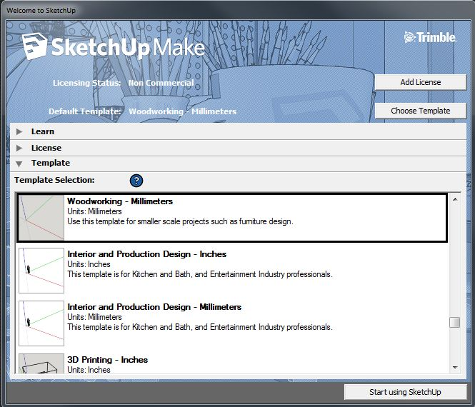
Check that you are using the same scale in both Aspire and Sketchup. If you use mm in one and Inch in another, this can cause confusion when you are importing to Aspire.
The only time you can change the measurements for Sketchup is to change the Template option when first opening the software.
- ► When I import my model, I get multiple copies of components.
-
When importing a model for vectors, any component attached to multiple layers will be imported multiple times.
To stop this select Only import visible data on selected layers and deselect all layers except for one instance of each component.
- ► When I import a flat panel with a rounded edge as a vector import it does not record the rounded edge.
-
2D vectors cannot record something from a 3D image, either use the 3D component import function, or approximate the desired curvature of your edge using a Profile tool path combined with a Roundover Toolbit.
As long as your material and toolbit settings are accurate to your equipment, the Toolpath Preview will accurately show you the final effect as long as there is no requirement for an undercut.
Undercuts cannot be viewed in Aspire or VCarve Pro.
- ► What version of Aspire or VCarve should I use to open SketchUp files?
-
You should use Aspire 4.514 and higher or VCarve Pro 7.514 and higher to open SketchUp files.
Always check for the latest updates using the Help Menu ► Check for Updates
Aspire 4.514 and VCarve Pro 7.514 can open Sketchup 2014 files and older.
Aspire 8.5, VCarve 8.5 and Cut2D 8.5 can open Sketchup 2016 files and older. (Vectors only for Cut2D).
- ► What sort of designs should I be using SketchUp for with Aspire and VCarve?
-
Sketchup and the Aspire/VCarve Pro Vector importer is designed to allow you to work smoothly with flat panel designs, which will allow you to visualise the final product before having the components pulled apart and made ready for cutting.
This will turn a 3D models edges into vector lines ready for you to assign toolpaths to.
Certain design aspects need to be considered in your Sketchup design to allow for easy importing, such as component naming and Layer ordering.
- ► What should I save my Sketchup model to import Vectors to Aspire or VCarve?
-
Aspire V4.514 and higher and VCarve V7.514 and higher can read Native Sketchup format (.SKP).
Load them from File Menu ► Import... ► Import Vectors...
Also you can now drag and drop .SKP files directly from a Windows folder into the 2D Drawing window to begin the Vector import process.
- ► What does Auto Orientate do in the Vector Import dialogue for SketchUp?
-
As most components want to be cut so that the largest face is face up on the CNC Router, if this option is selected, all the components in your Sketchup file will be rotated so that the face facing up is the largest.
If your design requires thin pieces that have a thicker profile then face, this option may not be suitable. Position your components within Sketchup with the correct orientation for cutting before importing.
If you are finding that your top face is not being used as the top face by the Sketchup Importer, (due to having a smaller surface area then the bottom face) then you can force it to stay the right way up by adding a colour to the top face in Sketchup.
Then when you are importing the vectors into Aspire/VCarve you can change the Orientation option to Orientate by Material and pick your colour from the dropdown menu. This will inform the importer exactly which way up you need the model be.
- ► My model does not look as smooth as it did in my other 3D package.
-
Most 3D packages apply a visual smoothing that makes a 3D model appear to be smoother than it really is.
Aspire will only show a 3D model as it really is, with no smoothing applied. This is to ensure that the on screen representation correctly resembles the final cut piece.
Once your 3D model is in Aspire, you can use the Smooth Components tool to take some of the edges off your model, but it is more effective to increase the polygon count within your 3D package and reimport it.
- ► My 3D SketchUp model is not importing to flat panels correctly in Aspire or VCarve
-
To recognise the models parts as possible panels to create vectors from, a Sketchup model needs to be modelled as individual components, rather than the entire design constructed as one piece.
Break the design apart into its individual component parts within SketchUp and reimport it.
- ► I have updated Sketchup and now cannot open my files in Aspire or VCarve
-
With the updates to Sketchup, their files have become version locked.
This means that our software can only open particular editions of Sketchup files.
Aspire V4.514 and VCarve Pro V7.514: Sketchup 2014 and earlier.
Aspire v8.024 and VCarve Pro/Desktop V8.024: Sketchup 2015 and earlier.
Aspire v8.5, VCarve and Cut2D Pro/Desktop V8.5: Sketchup 2016 and earlier. (Vectors only for Cut2D)
If you have a later version of Sketchup, then when saving a Sketchup file, you will need to change the Save as Type to an earlier version of Sketchup.
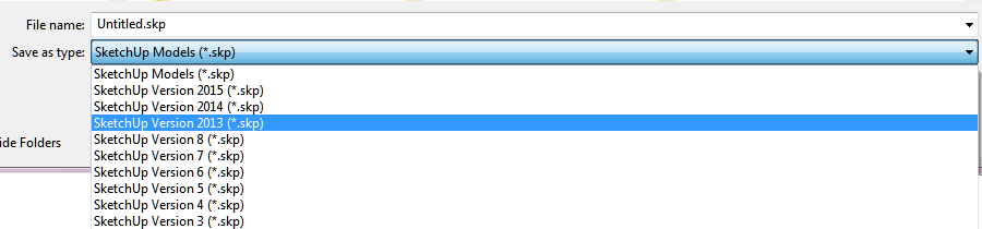
Saving a SKP fie this way will allow you to then import it into your Aspire and VCarve Pro/Desktop software.
- ► Why I can see through my model when it is imported?
-
Your model has a hole in it from when it was saved in Sketchup, reopen it in Sketchup and use the drawing tools to cover the hole.
Check the face orientaion to make sure the model is not inside out.
- ► How do I import SketchUp models?
-
For Aspire 4.514 3D components: Once you have a new project opened, or an existing project opened, use the File Menu ► Import ► Import Component/3D Model.
There are additional options to import and for more detail on this visit Aspire 4 Tutorial F03 Click here for Aspire Tutorials.
For VCarve Pro 7.514 and Aspire 4.514 Vectors: Once you have a new project opened, or an existing project opened, use the File Menu ► Import ► Import Vectors...
This will allow you to select your desired .SKP file and load the Sketchup File Import window.
From here you have various options to modify how the 3D Model is turned into 2D Vector lines that can be used in the software.
You can also use the Windows Drag and Drop to drop a .SKP file directly onto an opened projects 2D View which will begin the import process.
- ► How can I import a 2-sided SketchUp model?
-
Sometimes you want to machine a model that does not easily fit onto a flat plain for CNC machining. This can be handled just like any other 3D model import.
See our existing Tutorials on 2 sided machining here.
- ► How can I get the best results with the SketchUp Vector import?
-
If possible, take your Sketchup design and lay out the components flat with the pieces orientated as if you were laying them out to cut. This will ensure that when they are imported, the vectors are exactly where you want them to be.
When working with layers it is important to ensure that all parts of the element you are working with exist on the correct layer.
Due to the nature of Sketchups layers system, it is easy to spread a model over multiple layers, which will make importing it more difficult.
For more detail, please read the Sketchup Importing Guide.
- ► Can I import SketchUp models into Aspire/VCarve?
-
Yes you can.
Aspire can now load 3D models from Sketchup, in the exact same way you can from .STL files.
This is applicable for Aspire 4.514 and higher.
VCarve and Aspire can both now import 2D Vectors from Sketchup files.
This is applicable for both VCarve 7.514 and Aspire 4.514 and higher.
Toolpaths
- ► How can I open a file from Cut3D (V3D), Vector Art 3D Machinist (V3M) or PhotoVCarve (PVC) in Aspire, VCarve or Cut2D?
-
Yes, Aspire, VCarve Pro/Desktop and Cut2D Pro/Desktophave the ability to import the toolpaths that have been created in Cut3D (.v3d), Vector Art's 3D Machinist (.v3m) and PhotoVCarve (.pvc).
Once imported, the toolpaths can be used as part of the design in larger projects.
Note: While Aspire is capable of almost all operations the other programs can perform, the ability to import toolpaths from these programs was included to provide flexibility between users.
Here is an overview on how you would do this:
- You first need to setup and create the toolpaths in Cut3D, 3D Machinist (limited to Vector Art 3D's .v3m file format) or PhotoVCarve and save the file.
- Then in Aspire, VCarve Pro or Cut2D you would use the command File Menu ► Import ► Import PhotoVCarve or Cut3D toolpaths.
- Once imported you can use the visible grayscale of the image and position it where you want for the project's design. The program will then automatically provide an offset to ensure that is where the toolpaths will machine in your project.
Click here to find a Tutorial on Importing 3D Toolpaths into Aspire or VCarve Pro
Click here to find a two part Tutorial on Importing a 3D project into Cut2D
Note: Some tutorial material is written for Vector Art 3D's free 3D Machinist program. The steps for Cut3D would be identical.
- See Also:
- VCarve Pro 6 & Aspire 3 Tutorials
- ► How can I tell how deep my V-Carving is?
-
After the software has calculated a toolpath, it displays a summary of the toolpath data on the 'background' of the Toolpath tab. This is only visible when no other form is open on the Toolpath tab, so you may have to close the Preview form to see it.
As you click on different toolpaths names in the Toolpath List this information will be updated for the highlighted Toolpath. Find the Min. Z line and it will tell you the deepest that toolpath will cut.
As well as showing the Min. Z value for the selected toolpath, this information also includes feed rates, tool information and estimated machining time.
- ► Will my CNC do V-carving work?
-
Most modern CNC machines will certainly be able to cut 3D V-Carved projects. If your machine can move the X, Y & Z axes simultaneously (all at the same time), then it should be capable of V-Carving.
You can confirm that the software is compatible with your CNC machine by downloading the Trial Versions, opening the included sample projects and saving the toolpaths with the correct post processor for your CNC machine. Then you can actually cut samples at your machine and confirm it will work with the software.
If you have any additional questions, please contact us at This email address is being protected from spambots. You need JavaScript enabled to view it.
Click here to open the Trial Software webpage
- ► Why is the machined edge of my dish model rough or have a ridge around it?
-
Anytime you create a project with a dish or other recessed shape it is good practice to create a Zero Plane for the shape to merge with. This allows the software to better define the exact point where the recessed shape meets the surface, which will result in a better toolpath and smooth machined surface.
A ridge around the recessed shape could be caused by many reasons and they are typically associated with how the project has been designed and set up.
We cannot cover all the possibilities here, but one quick check you can make is to check is the Model Position in Material. Open the Material Setup form using the icon on the Toolpath Tab and verify the Gap Above Model is set to 0.0.
If this does not help, it is suggested you create a new post on the main forum and ask for possible ideas and solutions. Providing the file (only if it does not contain any protected 3D models or vector designs) always helps, as does pictures and screen prints. Normally, the more information you can provide the faster and better the responses will be.
- ► Why is no toolpath being calculated for the vectors I have selected?
-
There could be a few issues that would cause this and most should generate a Warning or Error message.
Some quick things to check include:
- Tool too large to fit in the area. Try increasing the size of the area slightly or Edit the tool and very slightly reduce the bit diameter just for that toolpath. For example, if you are trying to cut a pocket 0.25 inch (6mm) wide with a 0.25 inch (6mm) end mill you can adjust the pocket width or 0.251 inch (6.02mm) or edit to tool's diameter to 0.249 inch (5.98mm).
- Use node editing to check the vector(s) for small loops or overlapping segments. This is a very common problem when the vectors have been exported from another program.
If nothing is apparent, this type of problem is always good to post on the main forum and if the file does not contain any protected images or models, posting the file helps considerably. As a minimum, including some pictures and screen prints will help other forum members offer suggestions and ideas.
- ► Why does my actual cut part not look like the Preview Image?
-
The more you use our programs, the more you will appreciate the accuracy of the Toolpath Preview and how it can help achieve superior results at your machine.
However, there are issues beyond the program's control that can result in your machined project not looking like the Preview image.
There could be many reasons for this, but here are a few to consider and check:
-
Do not setup a toolpath that exceeds the cutting length for the bit you will use.
-
Be sure you set Z Zero at your machine to the same point (Top of Material or Top of Machine Bed) that was set in the program when the toolpaths were calculated.
-
Be sure you set the X,Y Origin to the same relative position at your machine that was set in the program when the toolpaths were calculated.
-
Be sure you have installed the same bit at your machine as the toolpath was calculated for.
-
For V-carving, it is very important to use the exact same angle V-bit as the toolpath was calculated for. A different angled V-bit may have been installed at the machine OR the actual angle is slightly different that what the bit manufacturer marketed it under. A forum member, Paul Z, has developed a quick and easy way to find out exactly what angle your V-bit is without the need for expensive measuring equipment. Click here to see Paul Z's guide.
-
Verify the actual Material Thickness matches the Material Thickness set for the project.
-
Double-check all the Tool Database setting for the bit you are using. Sometimes it is easy to create or copy a tool and input the wrong diameter.
-
Verify the Feed Rate and Plunge Rate settings are correct for your machine and material, and have the units you want.
If none of this helps, you can post your information on the forum to get other's ideas and suggestion or contact This email address is being protected from spambots. You need JavaScript enabled to view it. for assistance.
-
- ► When should I use a Start Depth?
-
You would typically use a Start Depth when setting up a toolpath that will cut where material has already been removed by another toolpath. When applied properly, this can result in significant time savings when machining some projects.
A good example would be where a Pocket toolpath has already removed 6 mm of material and you want to cut text at the bottom of the pocket that will be 3 mm deep. In this case, you would set the Start Depth to 6 mm and the depth you want the text to be cut, 3 mm, in the Cut Depth.
Note: When you have used Start Depth in a toolpath, always be sure to run the toolpaths in the correct order. For example, running the Text toolpath before the Pocket toolpath in the above example could result in bit breakage or poor results as the Text toolpath is now removing 9 mm but with the same setup that was intended to only remove 3mm of material.
- ► What is the difference between changing a tool's settings in the Tool Database and Editing a tool in the Toolpath setup?
-
When you change a tool's setting in the
 Tool Database, it changes the default settings for that tool and these are the settings that would appear the next time that tool is selected for a toolpath.
After selecting a tool for a toolpath, you have the option to Edit that tool and make changes to the default settings that will apply only to that toolpath.
- ► What is the "Solid" option?
-
The Solid Option is now a toolbar button: Toggle toolpath 2D drawing style (Wireframe or Solid)
An easy way to visually check you have correctly set up a 2D toolpath is to use the Solid option available on the Toolpath Tab.
First, make the toolpath visible by checking the box left of the toolpath's name, then check the box under the Toolpath List labeled Solid. This will place a solid blue line in the 2D window that represents the exact cut path and width of the selected bit and you can quickly see if the toolpath is cutting where you expect it to.
Tip: This is a very good way to visually see if the selected bit can fit into all the areas you want, such as profiling around text. If it does not, you can recalculate the toolpath using smaller diameter bits until you find the size that will work or make changes in the design.
- ► What do I need to reset after a tool change?
-
Once you have set the material up on your machine you need to set X,Y Origin in the same location in reference to the jobs position on your CNC as shown in the project's Material Setup. Once this is done, it is important that this is not changed or reset during the job because all the different toolpaths will reference from this point.
However, setting Z Zero accurately following each bit change is important to ensure accurate cut depths by each tool. Be sure to set Z Zero to either the Material Top or Machine Bed depending on how the project has been setup in the Material Setup.
Tip: It is a good practice to pick a spot and Z Zero every bit at that same spot during a project. Be sure to look ahead and don't pick a spot that may get machined away by one of the toolpaths.
- ► What controls the depth where the tabs are in a toolpath?
-
The bottom of tabs are always at the Cut Depth for the toolpath and extend upward by the Tab Thickness set during the tab setup.
If you set a Cut Depth deeper than the Material Thickness to intentionally cut past the bottom of the material, be sure the tab Thickness is enough to still appear in the material.
Also, when using a Start Depth other then 0.0 with tabs, if the Start Depth is below the top of the tabs, some or all of the tabs will be machined away.
- ► Saving Images with a plain background?
-
If you want to save an Image without any background color, which is a useful feature if the image is to be used in a brochure or other type of publication, follow these steps:
- * Select View ► Use Shaded Background to uncheck that feature
- * Save the image using the .PNG file format
- ► In the Profile Toolpath, what is Allowance Offset used for?
-
The Allowance Offset only applies to the Outside / Right and Inside / Left options. It provides a quick and easy way to calculate different size toolpaths using only one defining vector.
- For the Outside / Right option, a positive offset value will leave more material on the outside of a closed vector or to the right side of an open vector. Likewise, a negative offset value will remove more material from a closed vector or leave less material to the right side of an open vector.
- For the Inside / Left option, a positive offset value will leave more material on the inside of a closed vector or to the left side of an open vector. Likewise, a negative offset value will remove more material from the inside of a closed vector or leave less material from the left side of an open vector.
It is easy to visually check the toolpath in the 2D window to ensure the offset is doing what you expect by using the Solid preview option.
- ► In the Pocket Toolpath, what is Pocket Allowance used for?
-
The Pocket Allowance allows you to quickly create a toolpath that will machine the pocket either smaller or larger than the defining closed vector.
- A Pocket Allowance of 0.0 (the default) will create a pocket the exact size of the defining vector.
- A positive Pocket Allowance value will make the pocket smaller than the defining closed vector.
- A negative Pocket Allowance value will make the pocket larger than the defining closed vector.
It is easy to visually check the toolpath in the 2D window to ensure the offset is doing what you expect by using the Solid preview option.
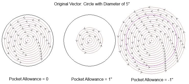
- ► How do Start Depth and Cut Depth work together?
-
When you set both a Start Depth and Cut Depth in a toolpath, the Cut Depth will begin at the Start Depth and add to it, so the total depth of cut will equal the Start Depth plus Cut Depth.
For example, setting Start Depth to 6 mm and Cut Depth to 3 mm will result in a total depth of cut of 9 mm.
- ► How do I use the two Safe Z settings, Z1 and Z2?
-
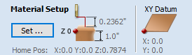
When you open the Material Setup form using the button on the Toolpaths Tab, you will see settings for Clearance (Z1) and Plunge (Z2). These are also referred to as the Safe Z settings:
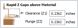
The Clearance (Z1) is the most important setting. This is the height above the job at which it is safe for the cutter to move at rapid or maximum feed rate. The software will raise the bottom of the cutter to this height when it traverses the material.
The Plunge (Z2) is an added feature. As well as specifying a rapid clearance gap for rapid positioning moves above the work piece, the user can also specify a much smaller gap that the tool will rapid down to during plunge moves.
- By default, the Plunge gap is set to the same value as the Clearance gap, which means that there will be no rapid plunges.
- If you set the Plunge (Z2) gap to a smaller value than the Clearance (Z1) gap, the tool will plunge at rapid feed rate to the specified distance above the material surface before changing to the specified plunge rate.
- For jobs where a large value for Clearance (Z1) gap has to be specified to avoid clamps etc, this feature can save a considerable amount of machining time if there are many plunge moves in the job.
- Setting a value of 0.0 for the plunge gap will also disable this feature.
Note: Not all machines can take advantage of this feature.
- ► How do I transfer the toolpaths to the machine tool?
-
There are exceptions, but the vast majority of users copy their toolpaths to some type of flash drive and take this to their machine or save over a network connection to transfer the post processed toolpaths directly to their machine's controller.
If that does not work with your machine, you should contact the machine's manufacturer or distributor to find out the required procedure.
- ► How do I stop the toolpath cutting past the edge of my 3D model?
-
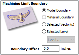
Aspire and VCarve V8.0 and Higher:
A new feature of Aspire and VCarve, is the option to automatically limit a 3D toolpath to the model boundary.
Just select this option when setting up your 3D toolpathing.
Aspire v4.5 and Lower:
If you select a closed vector shape before calculating the 3D Roughing and 3D Finish toolpaths, the toolpaths will observe the vector as a machining boundary and stay inside of it. Without this, the toolpaths will calculate for the entire surface of the material which can add significantly to the machining time.
There are a couple of ways to create this machining boundary vector. It may be as easy as creating a vector shape with the drawing tools (circle, ellipse, rectangle, etc.) or you may want a vector that follows the exact profile of the 3D model. In this case, you can use the
 Create Vector Boundary From Selected Components tool found on the Modeling tab or use the Trace Bitmap tool found on the Drawing tab.
Once the boundary vector has been created, the 3D Roughing and Finishing toolpaths include a setting called Boundary Vector Offset, which can be adjusted to allow the toolpaths to extend past the boundary by the set amount or have them short of the boundary by the set amount.
- ► How do I setup the start point of the toolpath?
-
For the Profile Toolpaths you can use node editing to place the vector's Start Point where you want it.
In Aspire and VCarve Pro, be sure to check the box that says Use vector start points (don't optimize) when setting up the Profile Toolpath.
In Cut2D, the default action is to use the vector start points under most conditions and the user has no external control over it.
- ► How do I set the Cut Depth when V-carving?
-
The V-carved Toolpath is unique because there is no way to set the Cut Depth. The toolpath requires a closed vector shape and will move the V-bit as deep as required to machine to the two vectors on either side of the bit.
In general:
- The wider the gap between the two vectors, the deeper the V-bit will cut.
- The narrower the gap between the two vectors, the shallower the V-bit will cut.
- The higher the included angle of the V-bit, the more 'pointed' it is and the deeper it will cut.
- The lower the included angle of the V-bit, the 'flatter' it is and will cut shallower
Note: As long as you have the Material Thickness accurately set in the Material Setup, the program will warn you if the depth of the V-carving will be deeper than the material thickness.
- ► How do I machine a single line font?
-
The Single Line Fonts included with the program are designed for drag type engraving tools using the
 Quick Engraving Toolpath.
However, you can machine them with ordinary router bits (typically V-bits or engraving bits) using the Profile Toolpath with the On option selected and a shallow Cut Depth set.
The Toolpath Preview will allow you to try different combination of bits and Cut Depths until you get the look you need.
- ► How do I ensure my bit will not hit a clamp when traveling across the machine bed?
-
When you open the Material Setup form using the button on the Toolpaths Tab, you will see settings for Clearance (Z1) and Plunge (Z2). These are also referred to as the Safe Z settings:
Clearance (Z1), which is also referred to as the Safe Z is the height above your Z Zero reference point that the bottom of the bit will rapid at across the machine bed.
If you are using clamps or have another need for the bit to travel above a certain height, this value is what you will set to control that.
- ► How can I remember what Allowance Offset or Pocket Allowance will change in my toolpath?
-
When you enter a positive value for either offset, it will always offset the cut line to leave extra material that would later be removed with a separate finish toolpath.
If you enter a negative value for either offset, it will remove more material than the defining vector would normally allow.
- ► How can I make copies of a toolpath to cut multiple versions of the same part?
-
Once you have setup a toolpath on one of the parts, double click on the toolpath name to open it for editing. Then select all the identical parts you want to toolpath and recalculate the toolpath.
Additionally, some control systems allow a single toolpath to be cut multiple times. This is totally a function of the control system and you would need to contact your machine's manufacturer or control system's developer for specific information.
- ► How can I machine a project which is larger than my CNC work area?
-
The
 Tile Toolpaths tool will break the entire project's toolpaths into smaller tiles that can be machined one at a time.
You have a choice of how you can break up the toolpaths which will probably be driven by your machine's size and the current project. The choices are to create individual tiles using separate pieces of material, which are later assembled to form the complete project or using one long piece of material you can reposition and machine it in sections.
You can find more detailed information in the Help Contents and view a tutorial video on the process in the Training Materials section.
Click here to open the Tutorial page with the Tile Toolpaths video
- ► How can I improve the edge quality of my 3D model when machining it?
-
It can sometimes be very challenging to obtain good vertical edges with 3D toolpaths.
If a vertical edge is part of the 3D design, there may not be much that you can do unless the model can modified and the design allows a vertical edge to be replaced with a slightly angled edge.
However, if the vertical edge is the outer edge of a design and will later be cut with a Profile type cutout toolpath, a good approach is to use some technique to limit the 3D toolpaths from cutting this vertical edge.
There are many ways to do this and the best approach many times depends on the shape of the 3D components. Some suggestions are:
- Use a boundary vector and set the Boundary Vector Offset to keep the 3D toolpaths on the top surface of the 3D model.
- Create a 3D component the same height (or close to it) as the edge you are trying to protect but larger in size and merge it with your project. Then use a boundary vector and Boundary Vector Offset that allows the 3D toolpaths to flow off the model and onto this new model a short distance. Finally, use a Profile toolpath (with normal tabs if required) to cut the vertical edges.
- Aspire Only: If the design was created with a Two Rail Sweep such as a molding, modify the Two Rail Sweep to add either a flat surface or angled edge (typically called a draft angle). Calculate the 3D toolpaths using the new wider vectors but cut it out using the original vectors with a Profile toolpath (with normal tabs if required).
- ► How can I improve the cut quality when working with difficult materials and/or deep V-carvings?
-
When cutting hard materials or very deep v-carvings the tool may vibrate or chatter causing marks on the job.
A tip for improving the surface finish is to:
- Calculate the toolpath using multiple Z Level passes
- On your machine - Set the Z Zero position for the tool slightly high (i.e. 0.02 inches or 0.5mm) and run toolpath 1. (this will leave material on the job)
- Calculate a second toolpath that cuts the job in a single pass (Be sure to set Pass Depth greater than the actual Min Z depth displayed for toolpath 1
- On the machine - Set the Z Zero position correctly and run toolpath 2. This toolpath will remove the remaining 0.02 inches / 0.5mm cleaning-up the surface finish.
- ► How can I get an estimate of how long the toolpath will take to actually cut?
-
You will find Estimated Machining Times associated with toolpaths found in different places depending on the program and the summary list below should help.
For all the programs, you have to take some steps to make this estimate as accurate as possible for your machine:
- First, set the Rapid Rate to the correct value and units for your machine. For most machines, this is set in the software that controls the machine.
- Then, actually time some toolpaths at your machine and adjust the Scale Factor for those toolpaths until the Estimated time for that toolpath is close to the actual time you measured.
- After you do this a few times, the best Scale Factor for your machine should become clearer.
Note: This is only an estimate and does not include any adjustments the machine's control system may make such as Acceleration/Deceleration settings. As such, it is hard to find one scale factor that will work with all the types of toolpaths. However, it should get you close and help with quotes and machining decisions.
Where to find the Estimated Machining Times:
- Cut3D: At the bottom of the Roughing, Finishing and Cutout Toolpath Setup pages and on the Preview Machining page where you can adjust the Rapid Rate and Scale Factor.
- PhotoVCarve: On the Preview & Save Toolpath page.
- Aspire and VCarve Pro: Click on the
 Toolpaths Summary icon on the Toolpath Tab that will open a summary sheet showing the individual times for all the calculated toolpaths and a Total Machining Time.
You can hover the mouse over the name of the Toolpath in the Toolpath List and the tool-tip will pop up with information about that toolpath including the Estimated Time.
Toolpaths Summary icon on the Toolpath Tab that will open a summary sheet showing the individual times for all the calculated toolpaths and a Total Machining Time.
You can hover the mouse over the name of the Toolpath in the Toolpath List and the tool-tip will pop up with information about that toolpath including the Estimated Time.
- ► How can I find the correct post processor for my machine tool?
-
After you click the
 Save Toolpath icon, there is a pull-down list with all the post processors currently stored in the PostP folder (in the Application Data Folder) on your computer. Scroll down this list, find and select the correct post processor for your machine.
You only need to do this once. The next time you open the Save Toolpath form the last post processor selected should show as the default post processor.
If you are not sure of the correct post processor for your machine, you can contact the machine's manufacturer or distributor, ask on the manufacturer's forum, ask on the Vectric Forum, or contact Vectric at . This email address is being protected from spambots. You need JavaScript enabled to view it.
- ► How can I create a new custom tool?
-
If you need to create a new tool that is not one of the standard types, you would create it as a Form Tool. With this feature you can match any router bit that does not have an undercut, such as dovetail bits and Keyhole bits.
You can find a detailed description in the Help Contents / Reference Manual and a How-To article at the link below.
- ► How can I control how many passes (depths of cut) my toolpath will take?
-
In most toolpaths you can set a Pass Depth for the selected bit. The program will create enough passes until it gets to the Cut Depth set for that toolpath.
In Aspire and VCarve Pro the
 2D Profile Toolpath can be modified using the button which opens the Specify Pass Depths form.
Tip: The ability to Edit Passes and quickly assign different pass depths is a quick way to leave an onion skin to be removed by a final pass. It also provides a quick way to adjust Profile toolpaths using bits such as v-bits and ball nose bits where the amount of material removed would increase with each pass if a constant Pass Depth was set.
- ► How can I adjust the depth of my V-carving when it is too deep or too shallow?
-
If your v-carving is cutting too deep you have a few options:
- The easiest solution is the use the Flat Depth option near the top of the V-Carve / Engraving Toolpath form. This will still cut angled sides using a v-bit but the bottom will be flat and limited to the Flat Depth amount. This can be visibly different than a design carved to full depth without a flat bottom, but may be your only option especially if you need to work with the v-bits you have on hand.
- Use a v-bit with a larger included angle, which cuts a shallower v-groove. For example, a 90-degree v-bit will cut shallower than a 60-degree v-bit, and a 120-degree v-bit will cut shallower than a 90-degree v-bit.
- Reduce the size of the vectors to reduce the gap. Typically not practical once the design is set, but may be one option if you have a limited number of different angle v-bits available.
If your v-carving is cutting too shallow switch to a v-bit with a higher included angle (more pointed).
Tip: Sometimes you may find the best angled v-bit for your project is one you don't have. Find out what v-bits are commercially available in your area and create tools for them in your tool database. Then use them with the Toolpath Preview until you get the results you want. Now you know exactly which v-bit you need to purchase to complete the project.
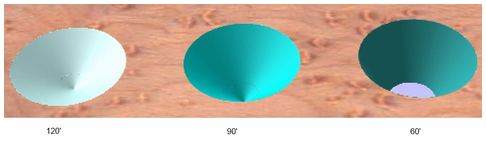
- ► Does Vectric software support Tool Changers?
-
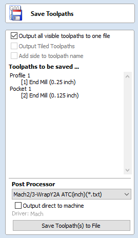
Cut2D and PhotoVCarve do not support tool changers.
Cut3D, VCarve Pro and Aspire all support Tool Changers assuming you have the correct post processor selected (the Post-processor name should end with ATC for Automatic Tool Change).
You can confirm this for your CNC machine by downloading the Trial Versions, opening the included sample projects and saving the toolpaths with the correct Tool Changer post processor for your machine. Then you can cut samples at your machine and confirm correct tool changer operation.
Each toolpath must have had its Tool Number set in the Tool Database (edit the toolpath and click the button).
The Tool Number is displayed in square brackets: [1]
Click Output all visible tool-paths to one file and all the visible toolpaths should be listed as shown:
- ► Can I create a tool with an undercut?
-
No, the Form Tool will not allow a bit with an undercut to be modeled since toolpaths using bits with undercuts cannot be previewed.
If you need to use a bit with undercut in a project, you can create a toolpath using a standard bit but run that at your machine with the undercut bit installed.
For example, you want to create a T-slot using a T-slot bit. You can create a toolpath using an end mill and preview that, realizing at your machine there will be a horizontal slot cut at the bottom of the toolpath. To do this safely and successfully, you need to have a good understanding of toolpaths, how to set up a single pass toolpath and possibly the use of Lead-ins and Lead-outs.
If you need help setting up a particular toolpath, asking on the Vectric Forum should get you the help you need.
- ► Can I control the speed of the Toolpath Preview?
-
Several settings can change the simulation speed when you preview a toolpath and the actual results will depend on your particular computer.
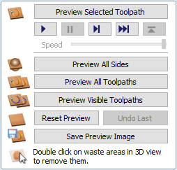
- Before previewing the toolpath, check or uncheck the 'Animate Preview' check box in the Preview Toolpaths menu. Having this checked will slow the preview down, having it unchecked will allow it to speed up.
- Changing the Preview Quality can make a difference on the amount of time it takes to generate the toolpath and preview it. The lower quality setting will allow the toolpath preview to go faster, but the resulting screen appearance will suffer. The higher quality settings will allow the preview go slower, but result in better screen appearance. You can change the Preview Quality by using Toolpaths ► Preview Simulation Quality.
- Aspire and VCarvePro add an additional feature called Preview Controls located on the Toolpath Preview form. These Preview Controls provide full video-like playback control of your toolpath. You can use this mode to analyze the tool moves in detail, moving step-by-step or until a tool retract. To begin using Preview Control, click on either the Run, Single-Step or Run to Retract buttons, which are summarized below.
- Aspire 4.0 and VCarve Pro 7.0 also add an option of a Speed Control slider which can be adjusted to slow down the speed that the toolpath simulation is run at.
- ► Can I add different types of preview materials?
-
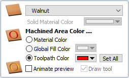
Although the standard list of job preview materials provides a reasonable selection of woods, stones and metals to choose from, you may have a project that requires a special material type. For example, a customer may require their work to be carved into a special wood that is not in the default list of materials.
The Job Preview material list can very easily be edited to include your own material types and selection names, allowing your work to be previewed and saved in the same materials that you are actually planning to rout or engrave.
- ► Are there any shortcuts for controlling the view in the 3D Preview window?
-
Yes, there are View Control shortcuts available to help with adjusting the view in the 3D Preview window listed in the 3D View Controls section.